Easy ESC Calibration using Arduino

Today we’re going to calibrate an ESC using Arduino Uno, so that it can used with a drone or any RC project. So, without any further waiting, lets get started

ESC

Today we're going to calibrate an ESC using Arduino Uno, so that it can used with a drone or any RC project.

So, without any further waiting, lets get started

What is an ESC ?

ESC is basically Electronic Speed Controller. As the name it suggests, it generates signals or voltage levels electronically through which we can control a BLDC motors speed precisely,  basically a PWM signal.

And why we need to calibrate it? Because not every BLDC is similar, some needs lil more current or less to achieve the same when used in pairs, or alone. So to set a start and a max speed points is necessary. Else we wont be able to control BLDC motor as we want it to.

What is PWM signal ?

PWM is basically Pulse Width Modulation. Pulse width modulation reduces the average power delivered by an electrical signal by converting the signal into discrete parts or chunks. In the PWM technique, the signal’s energy is distributed through a series of pulses rather than a continuously varying signal. ESC also uses PWM signals to control BLDC motor's.

What is BLDC motor ?

It is a type of motor, where electrical current is passed through coils that are arranged within a fixed magnetic field. Then the current generates magnetic fields in the coils causing the coil assembly to rotate, as each coil is pushed away from the like pole and pulled toward the unlike pole of the fixed field. Hence there is no need for brushes, unlike traditional motor.

What is an Arduino ?

Arduino UNO is a microcontroller board based on the ATmega328P. It has 14 digital I/O pins (of which 6 can be used as PWM outputs), 6 analog inputs, a 16 MHz ceramic resonator, a USB connection, a power jack, and a reset button.

It contains everything needed to support the microcontroller. Just simply connect it to a computer with a USB cable or power it with a AC-to-DC adapter or battery to get started. You can tinker with your UNO without worrying too much about doing something wrong, worst case scenario you can replace the chip for a few dollars and start over again.

Some of the key features of Arduino UNO -

  • ATmega328
  • 1kB EEPROM
  • Supported input voltage 4–12V DC
  • 1× UART, 1× I2C controllers, 6 × PWM channels

Hardware Requirements of this Project -

  • Arduino Uno
  • BLDC Motor
  • ESC
  • Lipo Battery
  • Jumper Cables

Software Requirements of this Project -

Now, lets move on to setting up of IDE and Libraries

Prerequisites and setting up -

Download or get Arduino IDE from their website/windows store.
After installing Arduino IDE, open it up can copy the following code onto a new sketch.

Circuit Diagram and Hardware Interfacing -

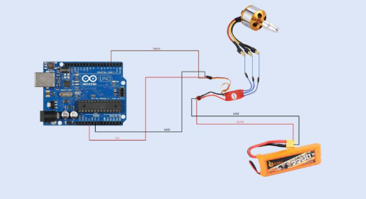
Circuit Diagram -

BLDC

Hardware Interfacing -

Arduino Nano -

Arduino Uno

ESC

+Ve 

+5V

-Ve 

 GND

pin 3 

Signal

Coding -

Copy the following code and pat it into Arduino IDE and after connecting Arduino UNO to your pc. Before you upload the code, make sure to select the correct port on which Arduino UNO is connected.

It should be automatic in newer IDE's, but in case it didn't auto select the PORT, assign the correct port in Tools section of the IDE. 

#include 


#define MIN_PULSE_LENGTH 1000 // Minimum pulse length in µs
#define MAX_PULSE_LENGTH 2000 // Maximum pulse length in µs

Servo motA;
char data;


void setup() {
    Serial.begin(9600);
    
    motA.attach(3, MIN_PULSE_LENGTH, MAX_PULSE_LENGTH);

    
    displayInstructions();
}

void loop() {
    if (Serial.available()) {
        data = Serial.read();
        switch (data) {
            case 48 : Serial.println("Sending minimum throttle");
                      motA.writeMicroseconds(MIN_PULSE_LENGTH);
            break;

            case 49 : Serial.println("Sending maximum throttle");
                      motA.writeMicroseconds(MAX_PULSE_LENGTH);
            break;

            case 50 : Serial.print("Running test in 3");
                      delay(1000);
                      Serial.print(" 2");
                      delay(1000);
                      Serial.println(" 1...");
                      delay(1000);
                      test();
            break;
        }
    }
}

void test()
{
    for (int i = MIN_PULSE_LENGTH; i <= MAX_PULSE_LENGTH; i += 5) {
        Serial.print("Pulse length = ");
        Serial.println(i);
        
        motA.writeMicroseconds(i);
        
        delay(200);
    }

    Serial.println("STOP");
    motA.writeMicroseconds(MIN_PULSE_LENGTH);
    
}

void displayInstructions()
{  
    Serial.println("READY - PLEASE SEND INSTRUCTIONS AS FOLLOWING :");
    Serial.println("\t0 : Send min throttle");
    Serial.println("\t1 : Send max throttle");
    Serial.println("\t2 : Run test function\n");
}

If the above coding steps are done without any mistakes when saving it onto  Pi Pico, then it should all work without any error.

Working of Project -

So, how this works is that when you power on the ESC and it sees an voltage on signal line, it goes into programming mode. And that level of voltage/ signal is saved as max throttle, and after that if we lower the signal voltage to a certain level, it saves it as cutoff/ stop signal.

And after it it'll beep few number of times depending on your battery configuration denoting number of batteries present in series in your pack.

After this, remove battery from the ESC and set your signal to low/ cutoff position. Now connect the battery. It should beep denoting the number of batteries in series in your battery pack and play a tone notifying it is now ready and armed.

If you were to increase throttle gradually, you should see your motor spinning faster and faster relative to your throttle/input signal. If everything works right, you've successfully programmed an ESC using Arduino. 

Note - We've used Servo library here to easily generate PWM signal ranging from 1000 to 2000 range. However there exists much efficient method's to calibrate and control ESC like D-shot, OneShot protocol's.

Conclusion -

Well, if you haven't encountered any problems or error's till this point then you have successfully calibrated an ESC using an Arduino. Now it is ready to be used in a drone or any other RC project.

Note - Always choose ESC rated higher than that of the motor's. And program them to 80% as MAX as this is to compensate for the change or little adjustments over then max throttle. For example, lets take a quad copter. If the motors were running at max speed, and it needed to balance itself out, it wont be able to because there is no more head room left for it to increase speed on one side thus resulting in destabilization or drifting over time.