HomeBlogs
How to Make a Line Follower Robot Using Arduino – Connection & Code
How to Make a Line Follower Robot Using Arduino – Connection & Code
As the name suggests, the line follower robot is an automated vehicle that follows a visual line embedded on the surface. This visual line is a path on which the line-follower robot runs. Generally, it uses a black line on a white surface, or you can adjust it as a white line on a black surface.
Usually, beginners and students would get their first robotic experience with this type of robot. We learned how to make a line follower robot with Arduino in this project-based article.
Line follower robots are used to assist the automated production process. They are also used in military applications, human assistance purposes, delivery services, etc.
Working of Line Follower Robot
The concept of the line follower robot is related to light. Here, we use the behavior of light on the black-and-white surface. The white color reflects all the light that falls on it, whereas the black color absorbs the light.
In this line-follower robot, we use IR transmitters and receivers (photodiodes). They are used to send and receive the lights. When IR rays fall on a white surface, they are reflected toward the IR receiver, generating some voltage changes.
Black surfaces absorb infrared radiation and do not reflect any of the rays that fall on them; therefore, no photons reach the infrared receiver.
In this project, when the IR sensor senses a white surface, an Arduino gets 1 (high) as input, and when it senses a black line, an Arduino gets 0 (low) as input. Based on these inputs, an Arduino Uno provides the proper output to control the bot.
Components Used in Line Follower Robot
Arduino Uno
IR sensor
L293D motor driver
BO motor
Wheels
Lithium-ion battery
Jumper cables
Also, it requires the robot chassis to mount all the above components on it. A robot chassis is an optional component; you can also make the robot chassis using cardboard.
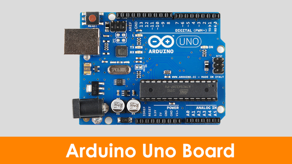
Arduino Uno
Arduino Uno is an 8-bit ATmega328P microcontroller. To support the microcontroller, it uses components such as a crystal oscillator, serial communication, voltage regulator, etc. It has 14 digital I/O pins( 6 pins can be used as PWM pins). It has six separate analog input pins, a USB connection, a power barrel jack, an ICSP header, and a reset button.
This board is programmable with the Arduino IDE (Integrated Development Environment) platform via a type B USB cable. This board can be powered via a USB cable or an external voltage ranging from 7 to 20 volts.
To know more about an Arduino Uno, refer to the article, what is Arduino Uno?
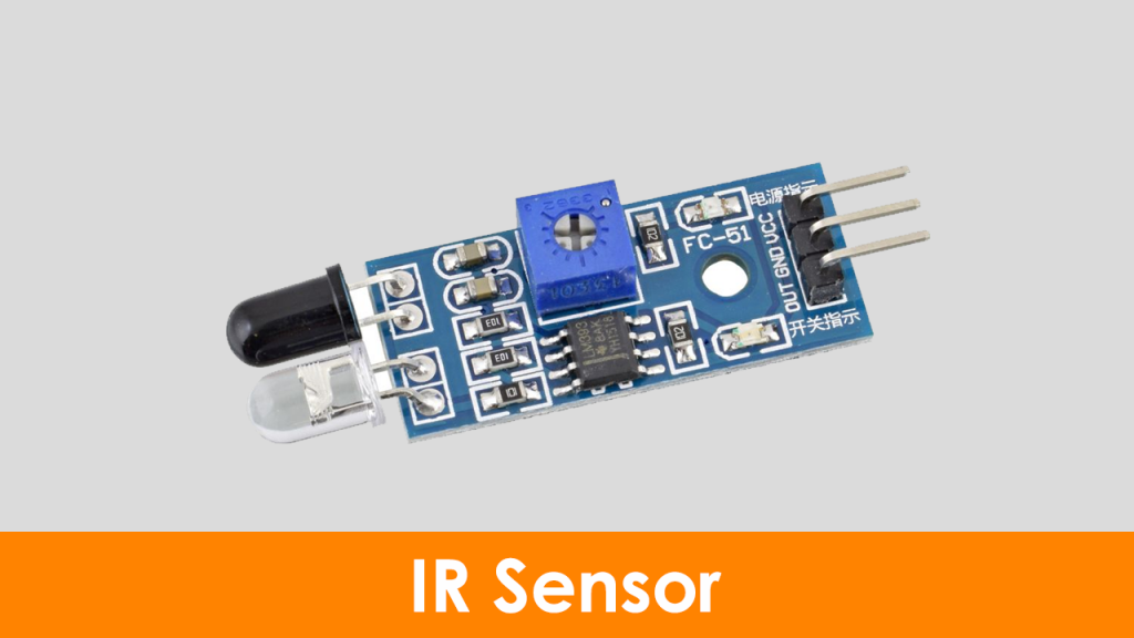
Infrared Sensor
An infrared sensor emits light to detect certain surroundings. In the infrared spectrum, all the objects radiate some form of thermal radiation that is invisible to our eyes, but an IR sensor can detect these radiations.
Here, the IR LED is an emitter, and the IR photodiode is a detector. An IR LED emits the IR light, and the photodiode is sensitive to this IR light. When IR light falls on the photodiode, the output voltages and the resistances will change in proportion to the magnitude of the received IR light.
The infrared detection system uses five essential elements: an infrared source, a transmission medium, an optical component, infrared detectors, and signal processing. Infrared transmission can be done through the vacuum, atmosphere, and optical fibers. To know more about the IR sensor, refer to the article on the working principle of IR sensors.
L298N Motor Driver
L298N is one of the easiest and best ways to control DC motors. It is the two-channel motor driver that can control the speed and spinning direction of DC motors.
This L298N motor driver is a high-power motor driver module. It is used for driving DC and stepper motors. This motor driver consists of an L298N motor driver IC and a 78M05 5V voltage regulator, resistors, capacitor, power LED, and 5V jumper in an integrated circuit.
When the jumper is placed, it enables the 78M05 voltage regulator. When the power supply is less than or equal to 12 volts, the voltage regulator will power the internal circuitry. When the power supply is more than 12 volts, then the jumper should not be placed and should give a separate 5 volts to power the internal circuitry.
Here, the ENA and ENB pins are speed control pins for Motor A and Motor B. IN1 and IN2 and IN3 and IN4 are direction control pins for Motor A and Motor B.
BO Motors
A BO motor is known as a battery-operated motor. These motors are commonly used in hobby-grade projects where the user requires a small DC motor as a simple actuator.
BO series linear motors provide good torque and rpm at lower operating voltages. The BO motors are available in single-shaft, dual-shaft, and DC plastic gear BO. These motors consume a low current. In this project, we have used four single-shaft BO motors.
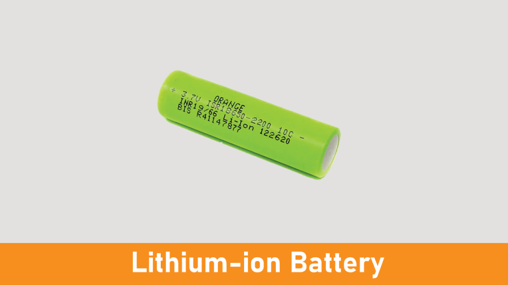
Lithium-ion Battery
A lithium-ion battery is a rechargeable battery. It is commonly used in portable devices such as mobiles, laptops, electronics, and electric vehicles. Also, they are growing in popularity for military and aerospace applications.
A lithium-ion battery provides 3.7V in storage mode and 4.2V in full charge mode. In this project, we have connected two lithium-ion batteries in series so that the total battery voltage will be 8.4V at full charge. To know more about lithium-ion batteries, refer to the article on the working of Lithium-ion batteries.
Connection Diagram of Line Follower Robot
Here, we have used four BO motors. Motors 1 and 2 are connected to the first channel of L298N, whereas motors 3 and 4 are connected to the second channel of the motor driver.
IN1, IN2, IN3, and IN4 pins are connected to pins 9, 6, 5, and 3 of the Arduino Uno. Here, we have used the jumper between +5V and the enable pins (EN1 and EN2). You can remove it and make the external connection, as shown in the below image.
Software & Programming Code - Line Follower Robot
Download the Arduino IDE software from the below link and upload the code to your board.
int mot1=9;
int mot2=6;
int mot3=5;
int mot4=3;
int left=13;
int right=12;
int Left=0;
int Right=0;
void LEFT (void);
void RIGHT (void);
void STOP (void);
void setup()
{
pinMode(mot1,OUTPUT);
pinMode(mot2,OUTPUT);
pinMode(mot3,OUTPUT);
pinMode(mot4,OUTPUT);
pinMode(left,INPUT);
pinMode(right,INPUT);
digitalWrite(left,HIGH);
digitalWrite(right,HIGH);
}
void loop()
{
analogWrite(mot1,255);
analogWrite(mot2,0);
analogWrite(mot3,255);
analogWrite(mot4,0);
while(1)
{
Left=digitalRead(left);
Right=digitalRead(right);
if((Left==0 && Right==1)==1)
LEFT();
elseif((Right==0 && Left==1)==1)
RIGHT();
}
}
void LEFT (void)
{
analogWrite(mot3,0);
analogWrite(mot4,30);
while(Left==0)
{
Left=digitalRead(left);
Right=digitalRead(right);
if(Right==0)
{
int lprev=Left;
int rprev=Right;
STOP();
while(((lprev==Left)&&(rprev==Right))==1)
{
Left=digitalRead(left);
Right=digitalRead(right);
}
}
analogWrite(mot1,255);
analogWrite(mot2,0);
}
analogWrite(mot3,255);
analogWrite(mot4,0);
}
void RIGHT (void)
{
analogWrite(mot1,0);
analogWrite(mot2,30);
while(Right==0)
{
Left=digitalRead(left);
Right=digitalRead(right);
if(Left==0)
{
int lprev=Left;
int rprev=Right;
STOP();
while(((lprev==Left)&&(rprev==Right))==1)
{
Left=digitalRead(left);
Right=digitalRead(right);
}
}
analogWrite(mot3,255);
analogWrite(mot4,0);
}
analogWrite(mot1,255);
analogWrite(mot2,0);
}
void STOP (void)
{
analogWrite(mot1,0);
analogWrite(mot2,0);
analogWrite(mot3,0);
analogWrite(mot4,0);
}
Final Output
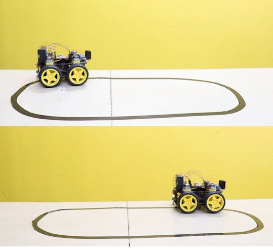
After uploading the code, if your bot is not running in the right direction, then change the wiring of the BO motors. Also, calibrate both IR sensors by varying their potentiometers.
The below GIF shows the workings of the line follower robot. Here, we have drawn the path on a white-colored surface with black color tape.
Final words
I hope this article helps you understand how to make a line-follower robot. Hobbyists can make this for fun projects as well as science projects.